Racking a few 9000 modules, so I thought I'd take some pictures as I went, and assemble them into a sort of a "How-To" for anyone else who wants to know how to do it.
To make things nice, the module is largely self-contained, and the inputs and outputs are already balanced. We'll be using Mic input and Line input, and taking the signal from the module's old Insert Send. This should still allow the dynamics to be switched pre or post EQ, as well as the dynamics sidechain switching, and if you want to wire the insert return up as a key input, you can even externally key the gate or duck the compressor.
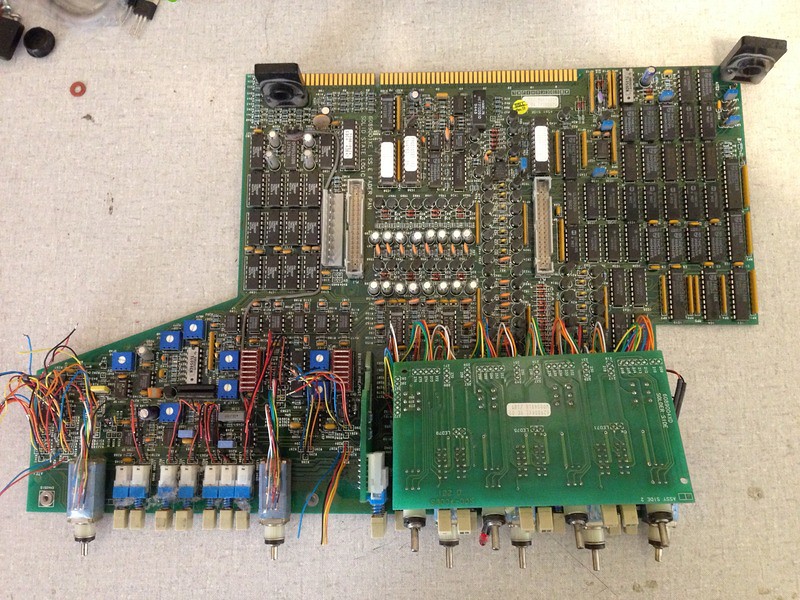
Here's how to start:You'll see the module is in two large circuit boards: the (smaller) lower PCB has lots of stuff we'll be discarding (like multiplexing, etc) while all the analog audio stuff we're interested in is on the (larger) upper PCB.
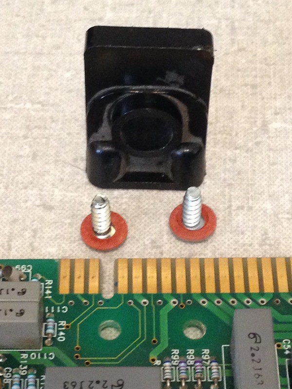
Start by locating the edge connector guide like the one shown in this picture:
 001
001 by
Keith Andrews, on Flickr
Specifically the one which has one screw hole in the upper board and the other screw hole in the lower board. You'll need to remove it in order to allow the two boards to separate.
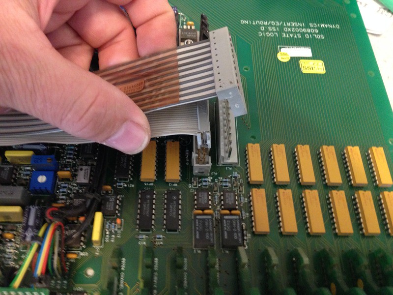
Next, unplug all the ribbons which link the upper and lower boards. On most modules there will be three ribbons (two are shown in this picture).
 002
002 by
Keith Andrews, on Flickr
On modules which have the optional Left-Center-Right pan option fitted, there'll be a couple more ribbons, going to a square circuit board mounted by the routing matrix... just unplug those too, and remove the circuit board too. (I'll dig up some photos of this board later, but it's easy-peasy. 4 screws is all.)
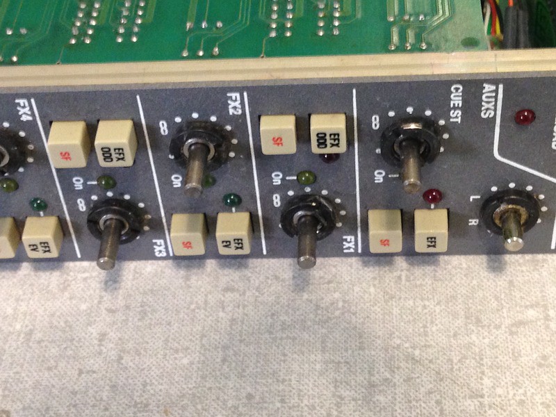
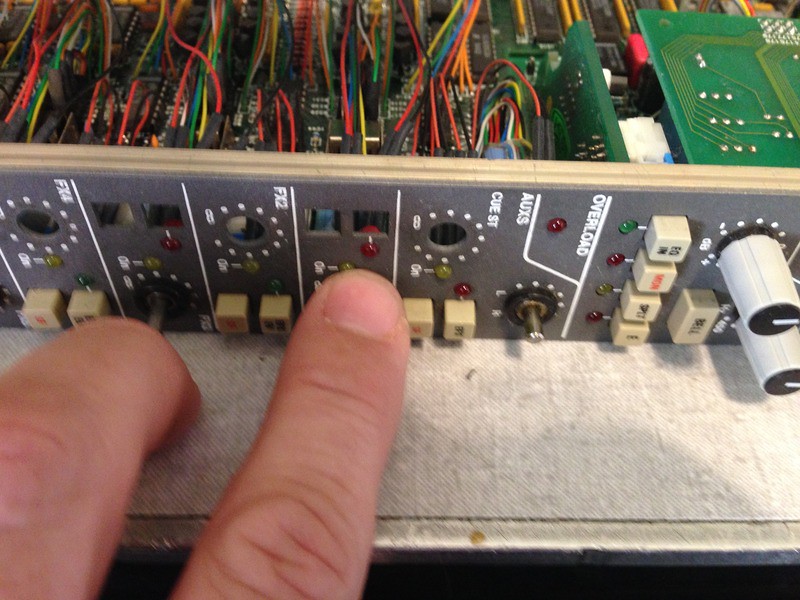
Next, remove the knob caps and knobs from the aux sends and pan pots. Basically all the knobs below the 'overload' LED.
 003
003 by
Keith Andrews, on Flickr
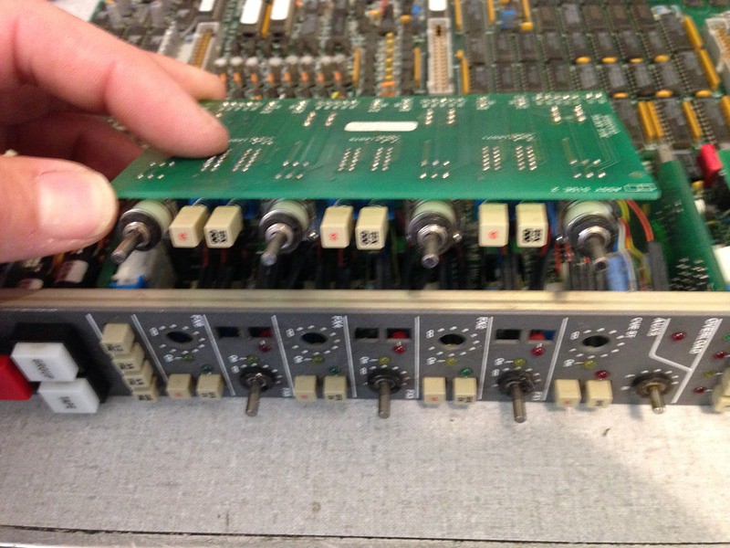
Next undo the pot nuts for the four pots which are mounted to the daughter board shown here. Then remove the board and lift it upward to reveal the LED wires attached to the same board.
 004
004 by
Keith Andrews, on Flickr
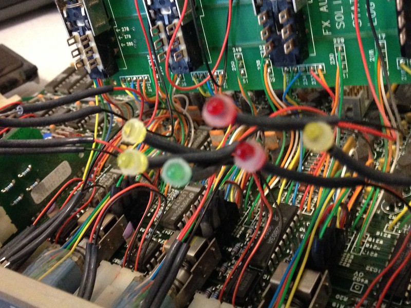
The LEDs are glued in... you can use needle nose pliers to remove them if you want, but you may just want to cut the wires, since we're discarding this whole thing...
 005
005 by
Keith Andrews, on Flickr
This is what the LEDs look like if you break them free from the panel...
 006
006 by
Keith Andrews, on Flickr
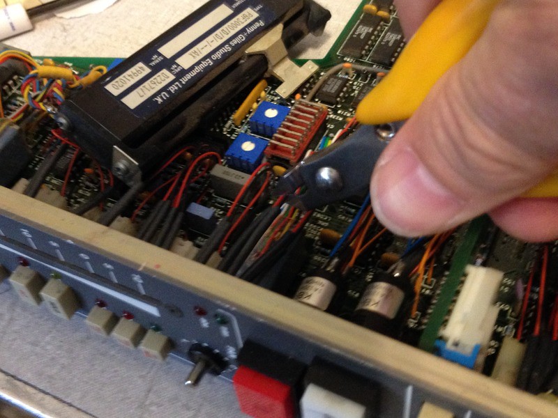
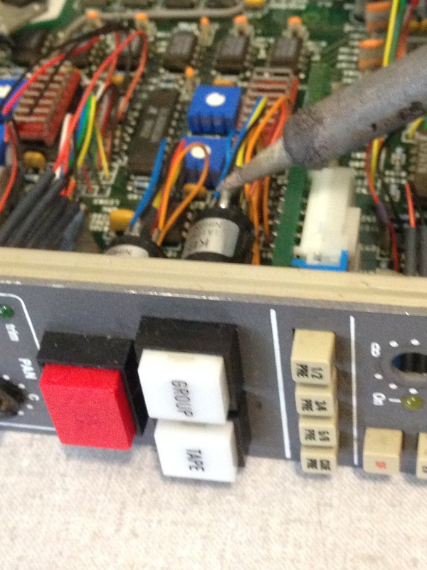
...but you may want to just cut the LEDs, since there's a lot of them, and they're hardwired... Here's me cutting some other LEDs further down the board...
 007
007 by
Keith Andrews, on Flickr
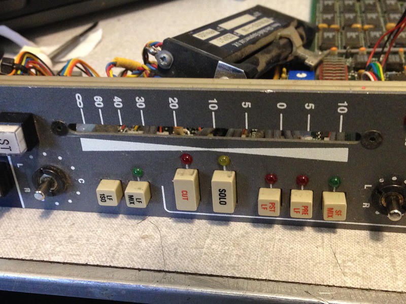
You'll want to remove the fader next... then the pot nuts.
 008
008 by
Keith Andrews, on Flickr
Then desolder the switch wiring... or if you don't care, just cut those wires too!
 009
009 by
Keith Andrews, on Flickr
Then flip the whole thing over and remove the three small countersunk pozidriv screws which hold the lower PCB to the front panel:
 010
010 by
Keith Andrews, on Flickr
Then remove the lower circuit board assembly... like this:
 011
011 by
Keith Andrews, on Flickr
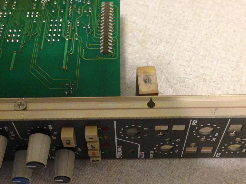
Next, remove the screw attaching the end-block to the module's lower edge...
 012
012 by
Keith Andrews, on Flickr
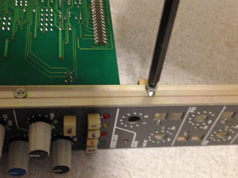
...move the endblock up to the uppermost liberated pcb mounting hole...
 013
013 by
Keith Andrews, on Flickr
...and re-attach.
 014
014 by
Keith Andrews, on Flickr
This makes a nice strong mounting point so you can 'chop' the unused part of the front panel.


